
Plasma speaker toy
Idea
This is one of my very first projects that I did with my father in elementary school. The idea behind having an electric arc play music is rather simple. The audio signal is used to modulate the high-voltage power supply, which then causes the plasma to vibrate along with the power changes. The simplest method of achieving this is utilizing a PWM modulator, setting it around 50% duty cycle and applying the audio signal as a duty cycle correction.
Electric circuit
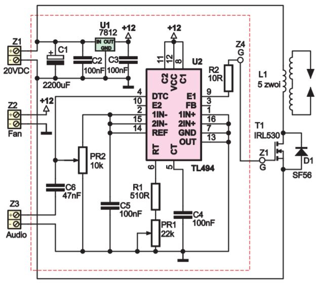
A typical circuit that creates such modulated oscillation is shown below (source). It utilizes the good, old TL494, which is primarily used to construct pulse power supplies of very different topologies. Here we use the built-in oscillator R1, PR1, C4 to generate the base frequency and PR2 to set the duty cycle. Capacitor C6 overlays a small AC audio signal over the DC base, causing the chip to regulate the duty cycle around a set middle point. The chip is used to drive a power MOSFET; in this schematic, it’s an IRL530, but I prefer using more powerful ones such as IRFP250N and others. This schematic is not, unfortunately, without issues. The main one has to do with how the MOSFET is driven by the TL494. In a nutshell, a MOSFET is a member of the field-effect transistor family, which means that it must be driven by changing the voltage across the gate and source terminals (the first and third connectors). However, the TL494 was designed to power bipolar junction transistors, which are steered by current; as a result, the chip has an open-collector output and can be used as a current source. I literally have no idea how this could be working in the first place, but miracles happen. This can be fixed in a crude way by adding a pulldown resistor between the gate and source of the MOSFET, but a better solution is to use a proper MOSFET transistor driver. By using the pull-down resistor, the turnoff time will be significantly longer, as the MOSFET will be discharging through a large resistance. This will cause the thermal losses in the MOSFET to increase.
The fixed schematic can be seen here:
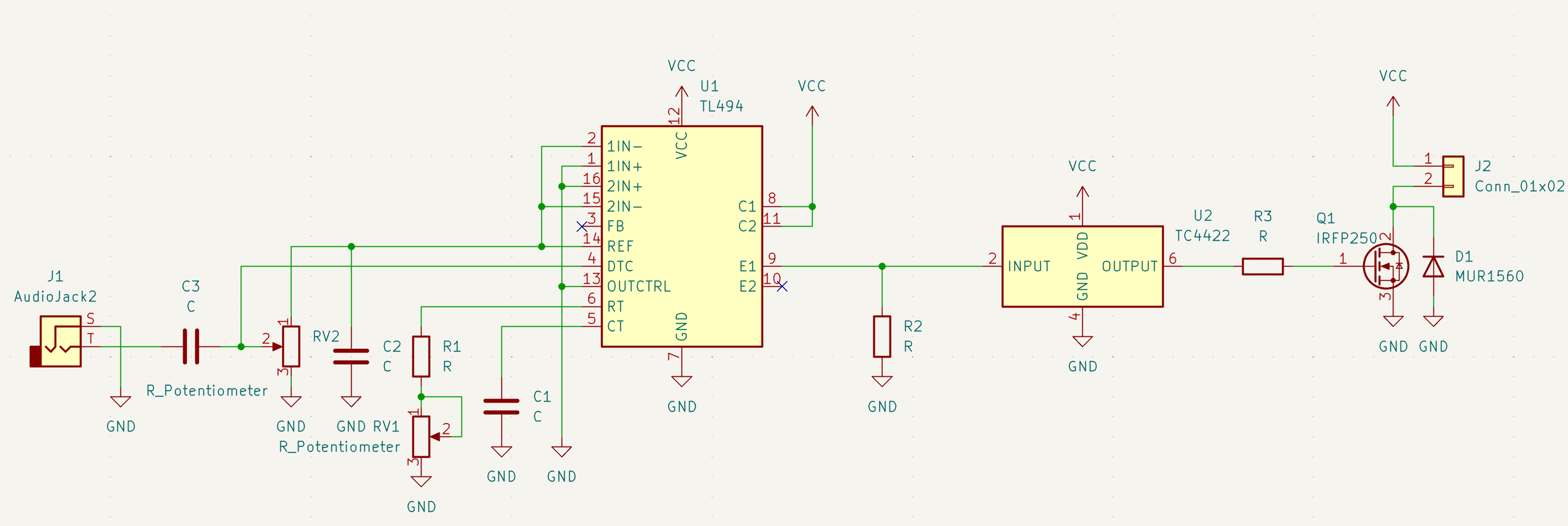
The added components are a pulldown resistor, which ensures that the signal reaching the MOSFET driver TC4422 does not have unknown states caused by the open-collector output only being able to source current. Any good driver can be used in this case. For driving larger transistors, I prefer the bigger 9 to 15 amp ones, such as the TC44xx family and IXDD6xx.
Assembled device
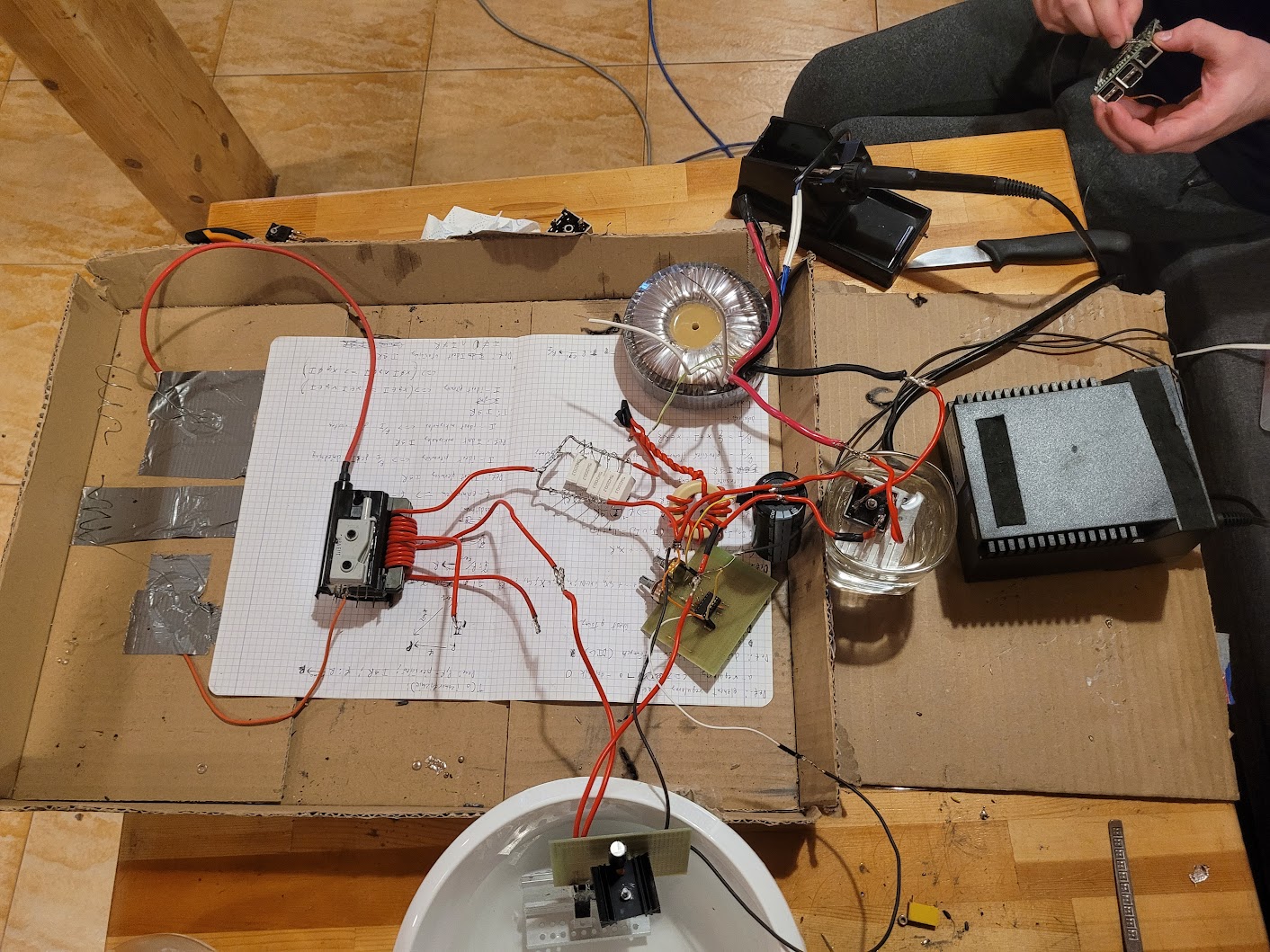
The photos come from a winter friends gathering where we decided to have some fun and construct this from scratch. It’s divided between two universal boards:
- controller with TL494,
- the power part with MOSFET and its driver.
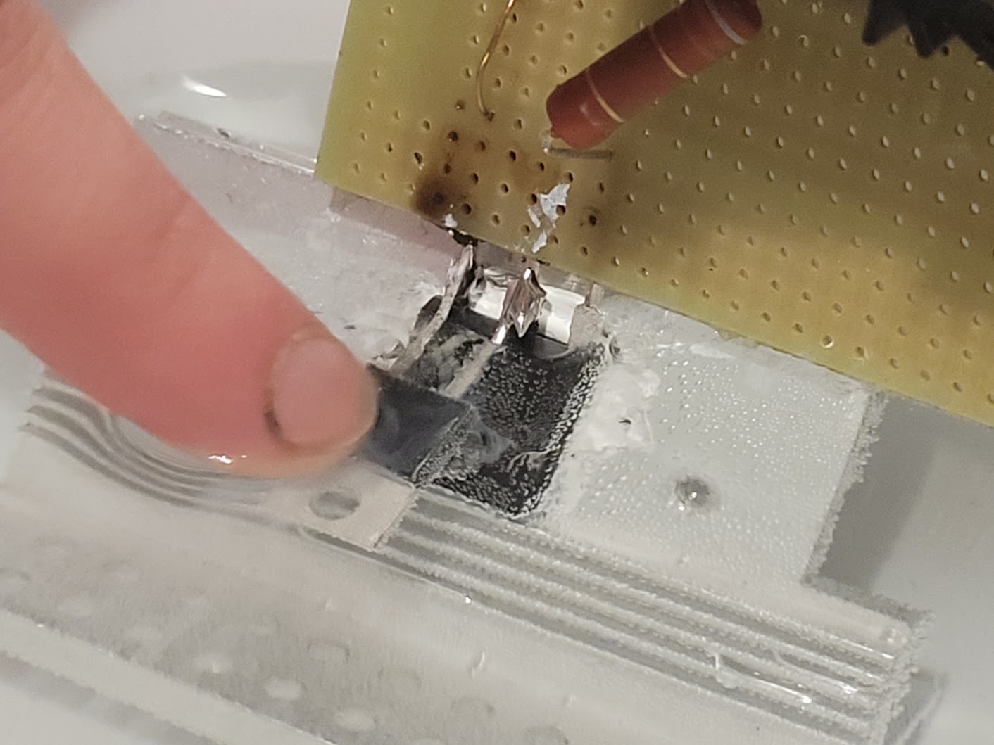
Since the MOSFET can get rather hot, we applied “poor man” water cooling by putting the MOSFET with its radiator into a glass filled with tap water. The device was powered by a toroid transformer that outputs 12V at 10A, with a bridge rectifier that we also decided to water cool. Our high-voltage transformer was a black HV transformer taken from an old tube TV with a new primary coil of about 10 turns wound on the external fragment of the ferrite core.
Things got hot when they were sticking above the water level. Additionally, some electrolysis was happening, but it didn’t turn out to be a big problem, and we didn’t plan to use this board after the meeting, so corrosion wasn’t a concern.
Result
We managed to get some nice electric arcs playing some meme music.
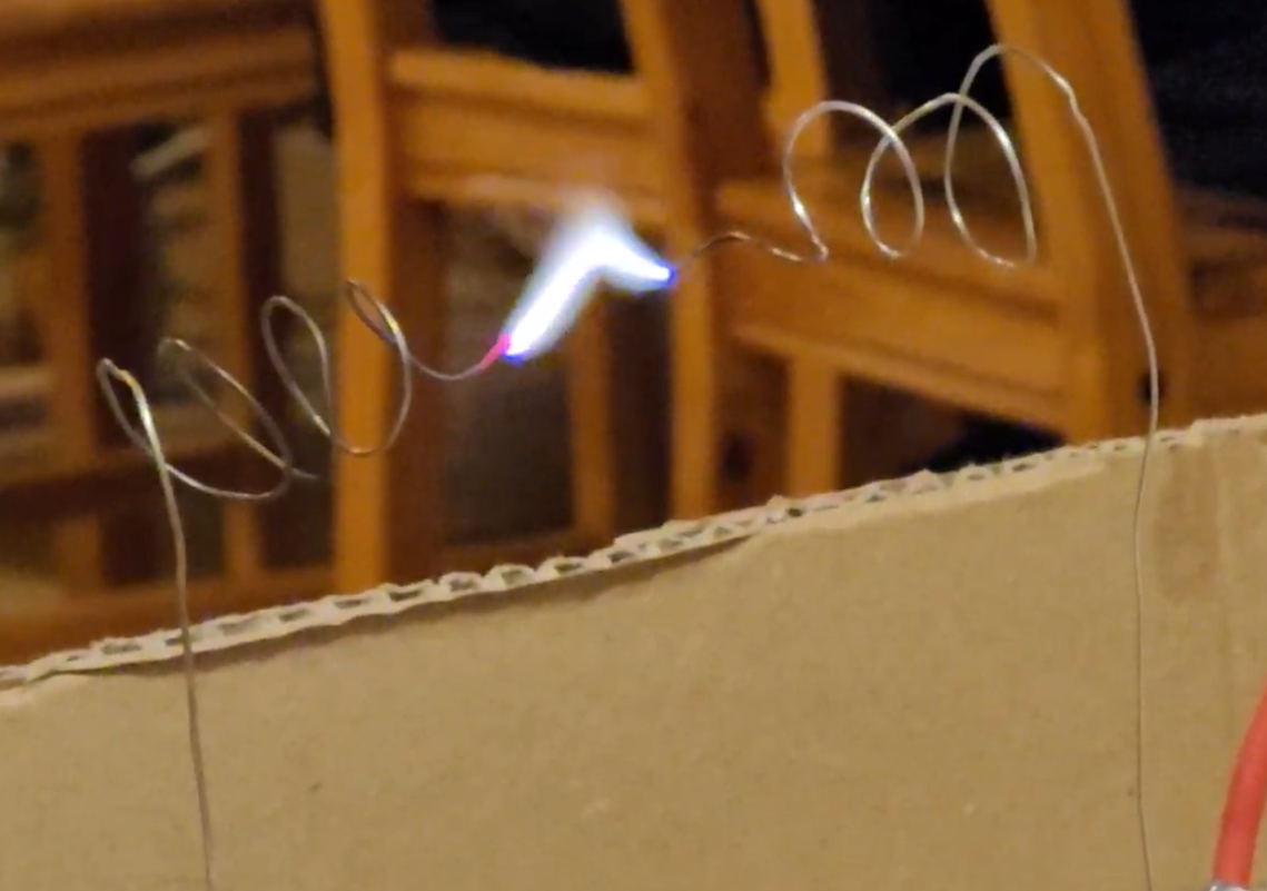
Playing “quacking in the 90s” :)