ESPHOME variable transformer
Idea
Finally, after many years of blowing full bridges with Tesla Coils and induction heaters, I decided to buy a variac. After some searching, I found an interesting one with a motor instead of a handle to control the output voltage. This was interesting to me, as I could create a remotely controllable variac that can be turned on, off, and adjusted from a safe distance to power any device. That’s why I decided to buy it along with a pre-made ESP12F board with 4 relays. This allows me to flash the ESP with ESPHOME and connect my variac to Home Assistant to allow for easy control. The ESP can also implement a PID controller to set the output voltage to a specified value given by the user.
Construction
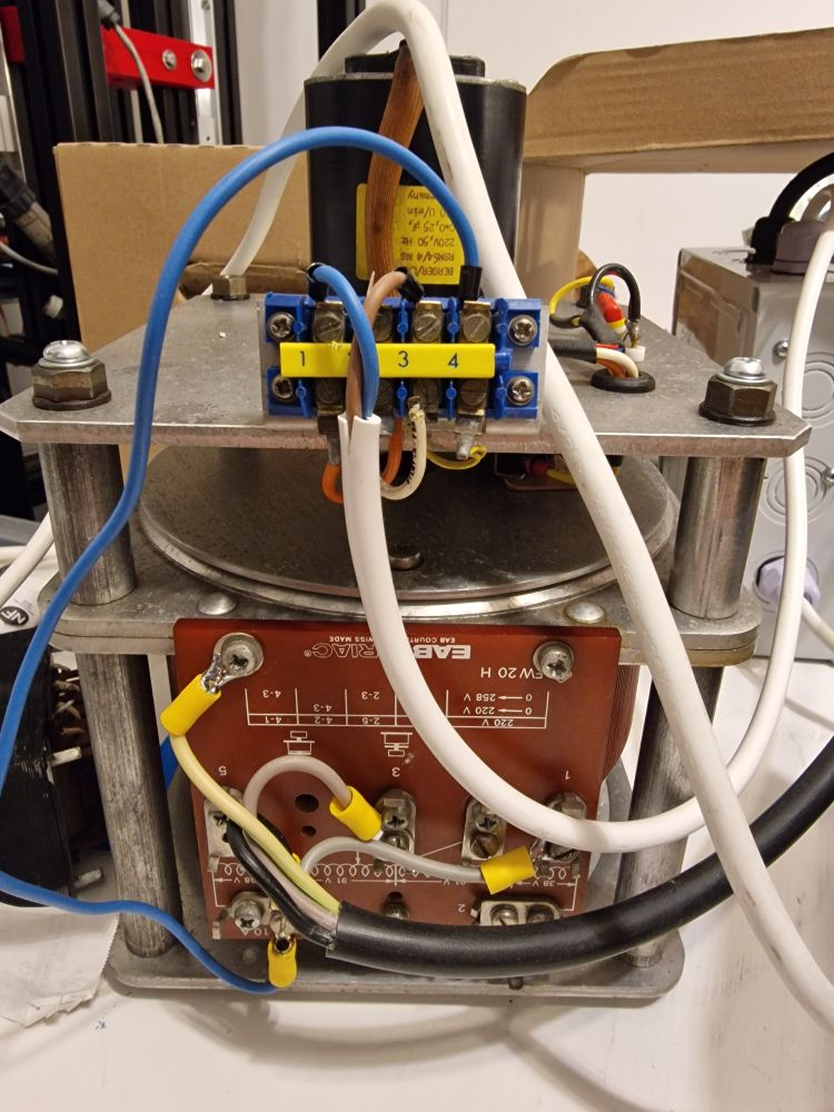
Naturally, the old device needed thorough cleaning after staying for years in a damp environment. The limit sensor for the engine required cleaning up and oiling. Fortunately, the device was working correctly, and after some minor tweaks, everything was in order. The next step was to construct the steering bow with the ESP control board. I decided to buy two big 30A grid relays, as I generally don’t trust the cheap 10A small-thy relays present on these boards. After trying to run it a couple of times, a soft start system was added, as the big toroidal core triggered the fuses in my flat too often during the initial core magnetization. To fit every component of the system, I bought a standard, cheap, plastic box, did some drilling, and tried to force everything inside. This is how it looked initially:
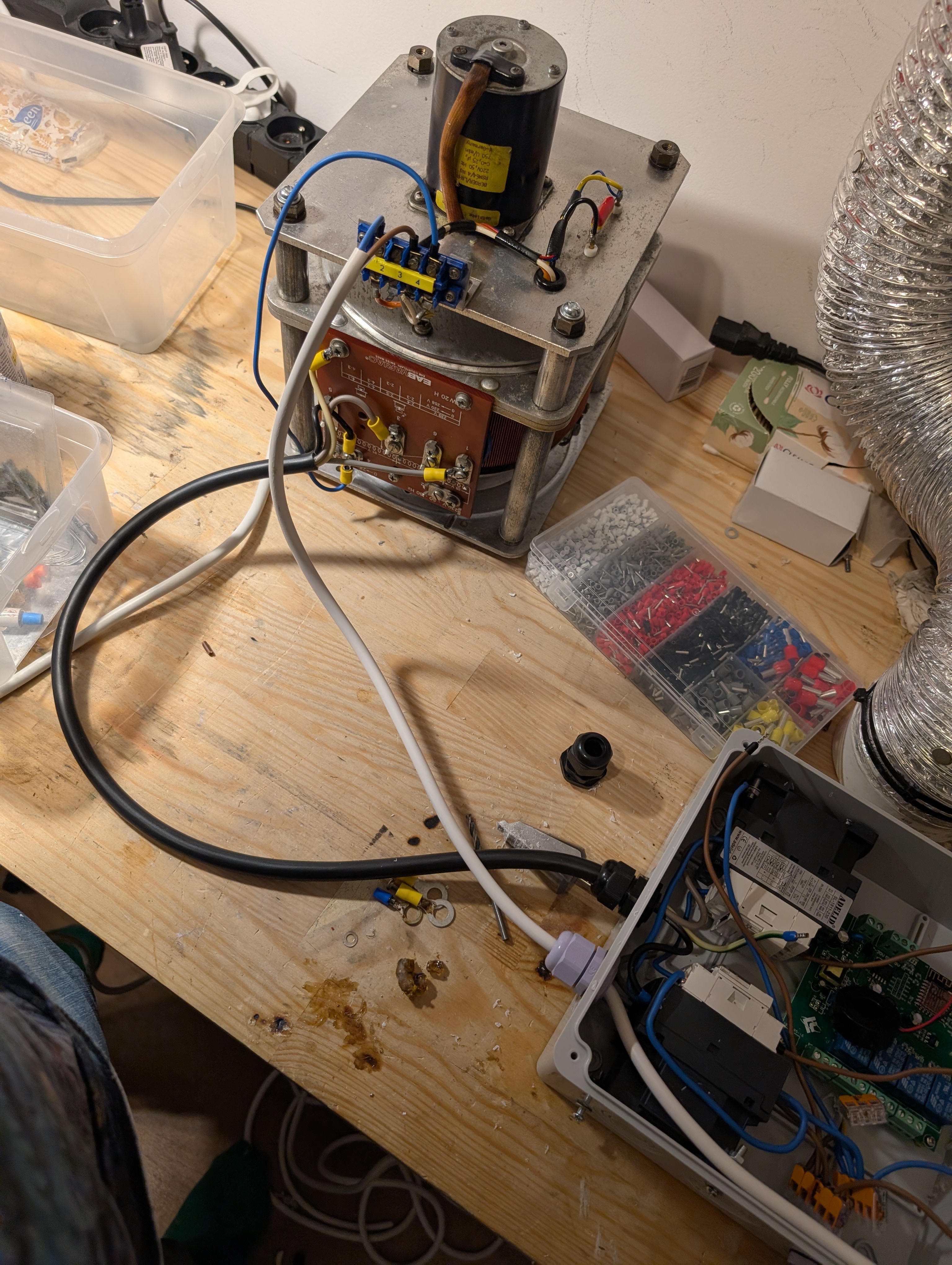
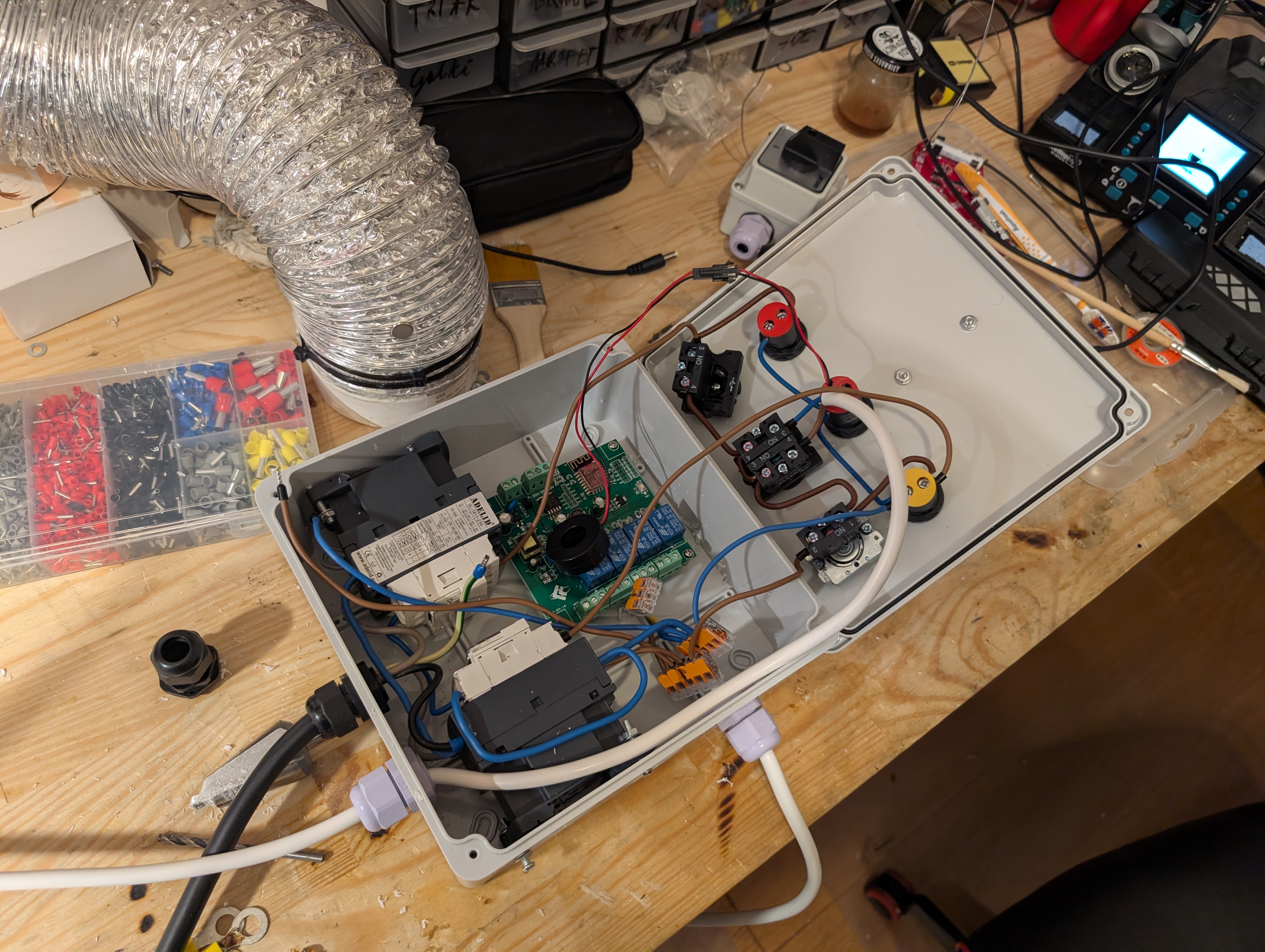
The front panel features also manual switches to control the device without the need to talk with the ESP module. This was a deliberate choice, as in my personal opinion, when some appliance is too smart and lacks easy-to-use and extensive analog controls, it’s just garbage. The most recent version of the front panel has 3 buttons:
- red safety button, which controls the relay powering up the primary coil,
- voltage adjustment switch, which when turned left or right either decreases or increases the voltage,
- the output control switch, which powers the relay connecting the output socket with the secondary connector on the variac.
Additionally, we have 3 indicators:
- a green light, which shows whether the transformer is powered up,
- a simple multimeter showing the voltage and current in the secondary loop,
- the red light indicating whether the output socket is connected to the secondary.
The current front panel looks like this: 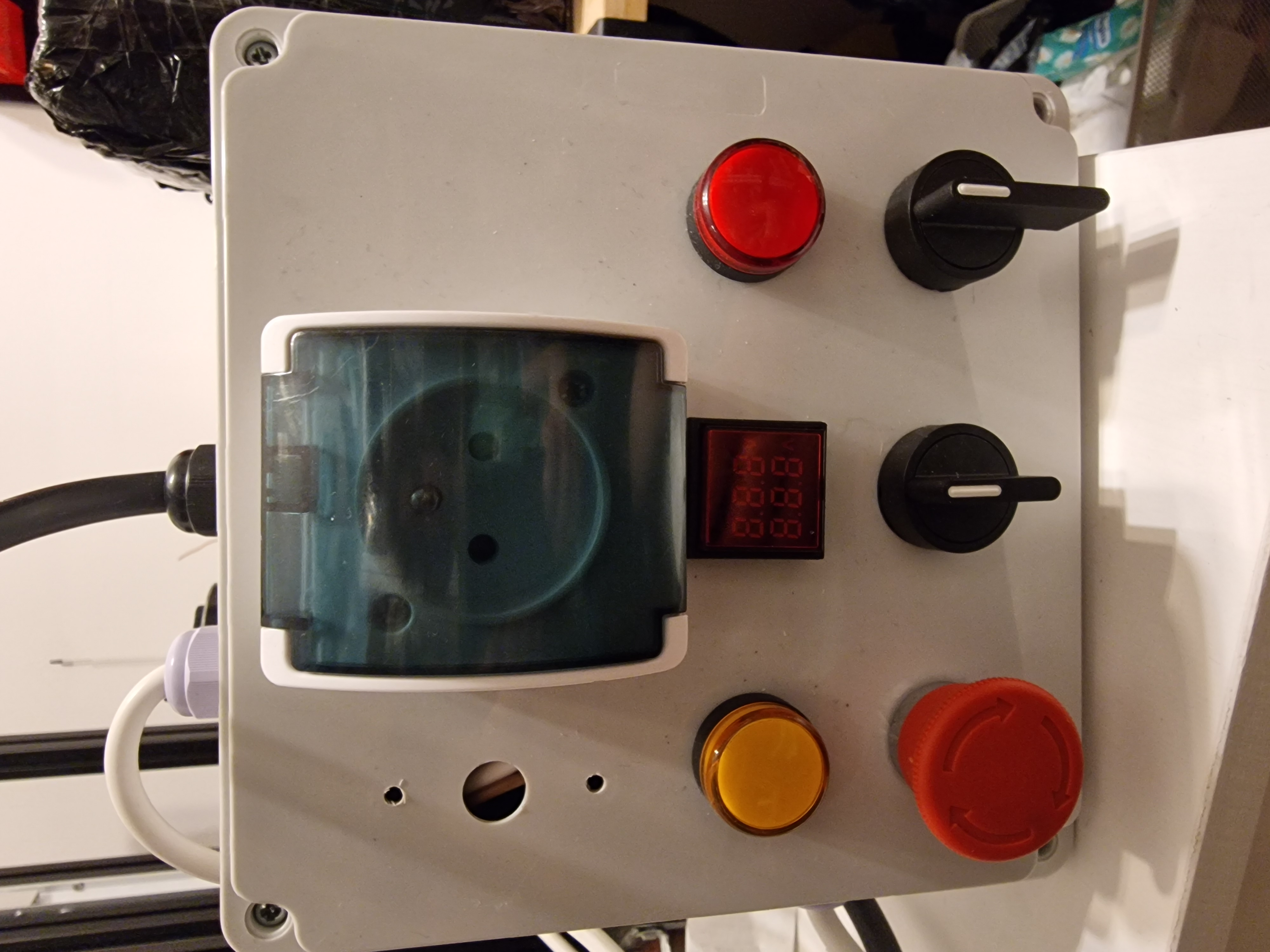
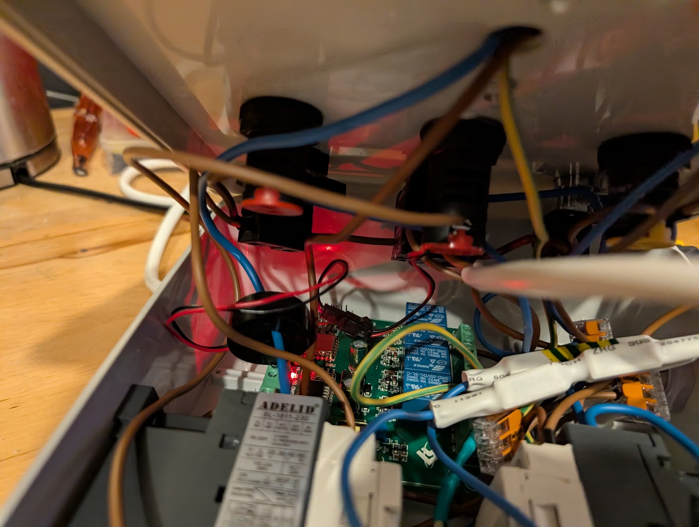
When all components were inside the box, it got a bit crowded there.
Firmware
I really can’t state anything sophisticated here; we just generated some YAML for ESPHome using an LLM, and it worked :).
Testing
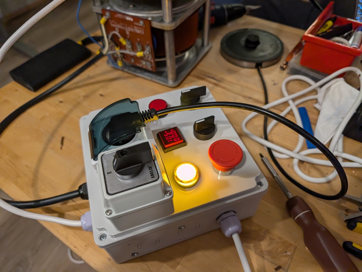
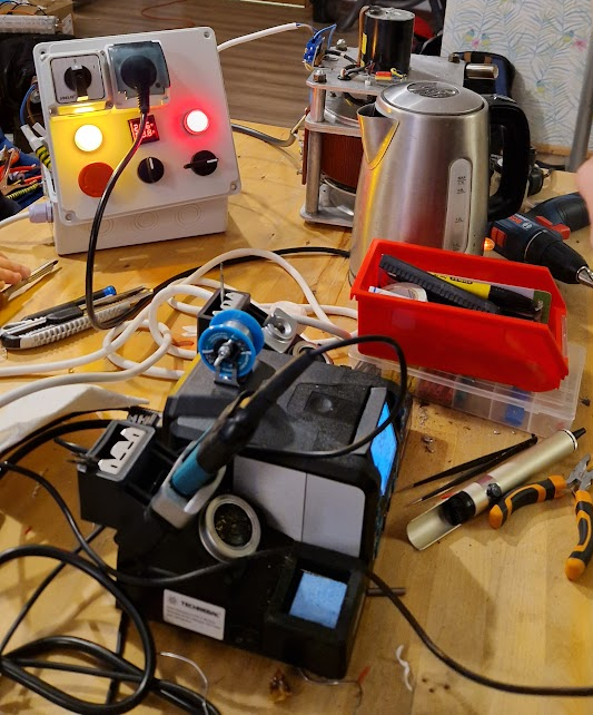
The device was tested on an electric kettle, where we tested under- and over-clocking. This variac allows boosting the voltage a bit to about 260V, so we can get hot water a little faster.
Home Assistant integration
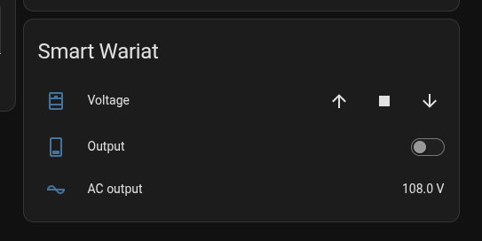
Thanks to using ESPHome, this device can be easily integrated into Home Assistant. This finally makes this device “smart.” The next step would be to add an LLM inside. Jokes aside, the next step would be to optimize the output voltage meter, as currently the ESP measures AC voltage and performs numerical integration, which is time-intensive and causes the WiFi connection to be quite unstable.