
Marx generator toy
Idea
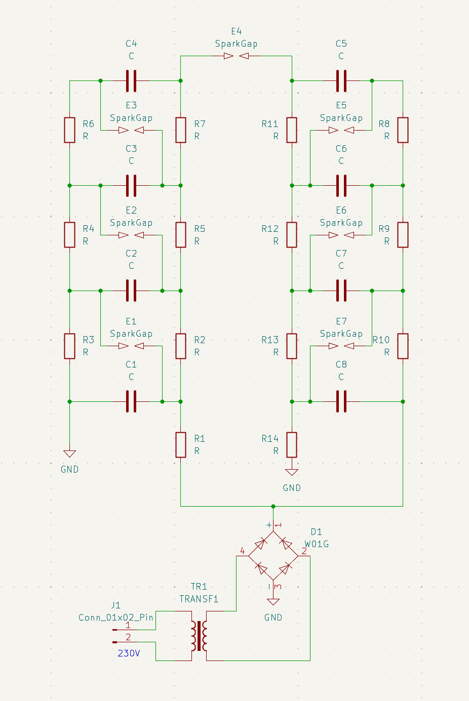
The Marx high-voltage generator is one of many that relies on charging a block of capacitors in parallel and discharging them in series, thus adding the voltage. The generator consists of n stages, where each stage is built from:
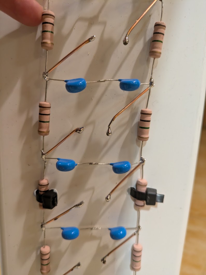
- The BIG resistor, which needs to have large resistance in the range of several MΩ so that when the discharge arc becomes the path of less resistance. Additionally, they need to be rather large when it comes to dimensions to resist the capacitor charge voltage; otherwise, the high voltage may jump over this resistor, causing heat damage and preventing the generator from charging further stages. (This prototype actually suffered from this; I should have used 2 2W resistors)
- The capacitor, which is storing the charge to be multiplied; it needs to withstand the power supply voltage and have capacitance of the order of several nF. The bigger the capacitance, the more energy is discharged into the final arc, but the generator requires more time to charge up. This construction utilizes ceramic 1nF10KV capacitors connected 2 in series to get 20KV breakdown voltage.
- The spark gap, which connects the neighbouring stages in series. It’s just a pair of copper wires connecting the capacitor’s right leg with the left leg of the complementary capacitor in the next stage. The edge of this wire is finished with a solder ball to limit the losses from phenomena such as corona discharge, which likes to leak electrons from sharp edges when large voltage is applied.
The simplified schematic of this device is provided below:
Power supply
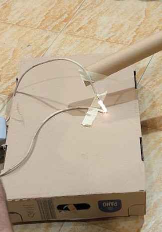
The power supply for this device was chosen to be an old neon transformer capable of delivering about 10KV at 45mA. This is more than necessary to run such a device. Naturally, the transformer current needs to be rectified, so a high-voltage rectifying bridge was built. It was composed of 80 1N4007 diodes connected in series to produce a full-wave rectifier 4x (20 in series). Below you can see the spark from the transformer alone; it’s about 10mm in length, which is consistent with the expected voltage.
Assembly
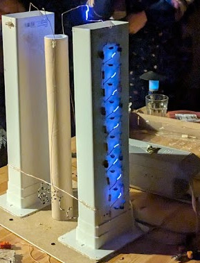
The multiplier stages were constructed on top of a PVC tunnel that was supposed to be used to move air in ventilation systems. In general, any good insulator that has some mechanical strength is good. This was just easily available at the local hardware store. The next image shows a close-up of the finished stages.
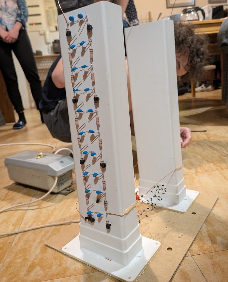
To get higher voltage quicker, two towers of 10 stages were built. This works exactly like a single 20x single multiplier tower but charges quicker, as here the two shorter towers are connected in parallel. Of course, those towers must be of opposite polarity for this to work. As it can be seen on the schematic, the two towers are connected anti-parallel to the rectifier. In between the towers, you can see the rectifier consisting of coiled chain of 1N4007 diodes.
Result
The main issue with getting this thing to work turned out to be tuning the spark gaps to fire simultaneously. Trying to align the ends of the spark gaps and tune the gap length took a long time. Fortunately, the generator produced some sparks like this:
Sadly, its performance was limited by the occasional ignition of the charging resistors.