ESP32C6 board for remotely controlled projects
Links
Idea
The idea for this board was born when I received an old clock from a Polish train station. These clocks are essentially simple DC motors, which require about 15V to turn reliably. I just needed to make some nice controller with battery backup power, Wi-Fi to connect to an NTP server, and drive the motor. The more I was designing, the more features were added, and at some point during the happy overengineering process, I began to think that I could actually use this board for many other projects, not just only driving some old clock. That’s why I decided to generalize a bit the IO connectors so as not to limit the usefulness of the ESP32C6.
Naturally, the firmware for this board is written in Rust as a
way to torture the programmers with uncompleted HALs, which aren’t
production ready and still lack many important features.
Board features
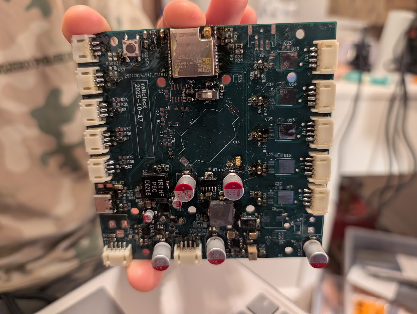
This board features:
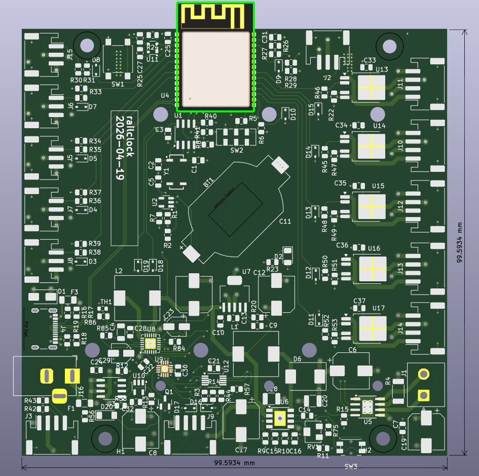
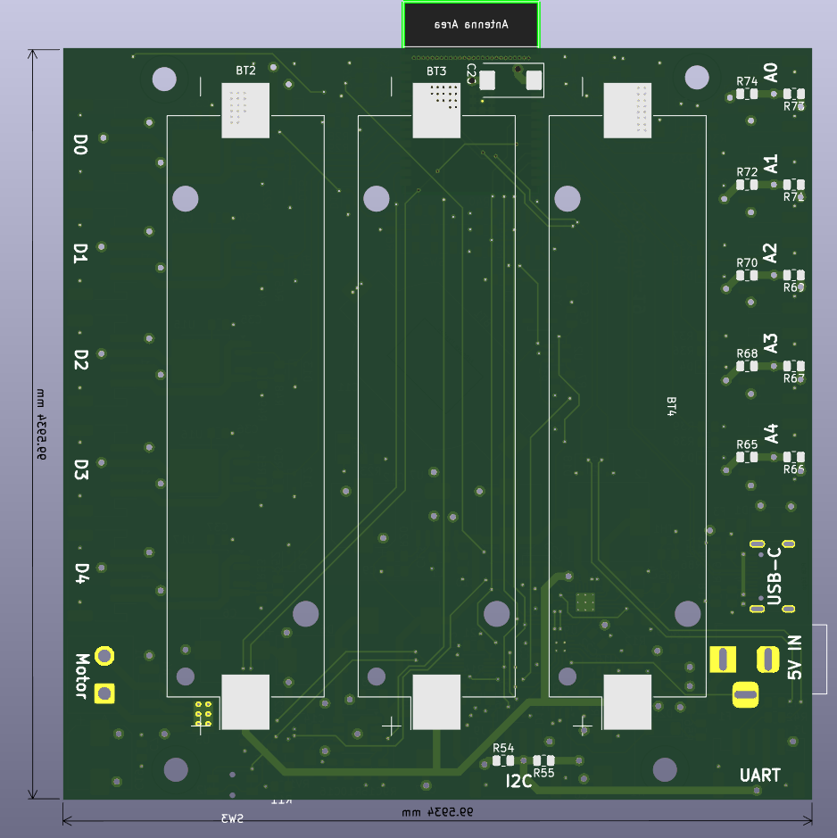
- 11 accessible GPIOs on JST connectors (5 ADC-capable ports on the left, 5 digital/drive outputs on the right).
- Left side ports: ADC-capable pins and a selectable 5V supply (powered by on-board 5V regulator/charger when available).
- Right side ports: digitally-driven output stage able to source up to 12V and ~800 mA (per port design limits depend on load and thermal conditions).
- On-board power management:
- BQ24296M battery charger to accept battery power and produce the 5V line when no external USB is present (the USB OTG feature of the charger is abused to bring up the 5V line without another boost converter).
- PAM2421 boost converter to generate the 12V rail from the battery/5V bus.
- Motor driver: DRV8870 used to drive DC motors from the 12V rail.
- RTC clock MCP7940n with separate battery.
- Up to 3 18650 Li-on cells connected in parallel.
Designed PCB